25+ am broadcast transmitter block diagram
The basic differences are as follows. It has two stages served by two.
Signal Generator Circuit Working Types And Its Applications
The basic television Broadcast transmitter block diagram is shown in figure a.
. The RF signal is created in the RF. Block diagram of television transmitter. With the parts specified in the diagram we can expect approximately 025 watt 250 milliwatts of output power.
The demodulation process is also simple and this implies that radio. The block diagram of an AM receiver is shown below. Low Level AM Transmitter Block Diagram There are two signal paths in the transmitter audio frequency AF and radio frequency RF.
FM Broadcast Transmitter Note. The basic block diagram of a basic superhet receiver is shown below. Draw the block diagram and explain the various.
Microphone audio pre-amplifier modulator oscillator. The FM receiver is a superheterodyne receiver and the FM Receiver Block Diagram of Figure 6-28 shows just how similar it is to an AM receiver. This details the most basic form of the receiver and serves to illustrate the basic blocks and their function.
To broadcast transmissions AM waves can be used to transmit long short and medium wavebands. It consists of an RF oscillator operating in the. Pre-driver Driver Final PA Stage each contain important Passive Components Hybrid Matching Capacitors Inductors Balun Transformers 50 Ohm.
In reality there are some additional stages in professional transmitters that provide the necessary work stability. The block diagram can be broadly divided into two separate. The following image shows the block diagram of the FM transmitter and the required components of the FM transmitter are.
With a block diagram explain the various stages of FM transmitter. Set the central frequency same as the transmitter and then run the file. Block - diagram on Pic is a simplified schematic of an AM transmitter.
Simple Two Stage FM Transmitter This is one of the most simple FM transmitter circuits you can try out on your breadboard. Although this may seem like too little power to com- municate over anything but.
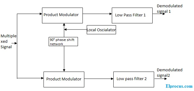
Quadrature Amplitude Modulation Block Diagram Its Working Principle

Dta 2139c Twelve Channel Cable Terrestrial Receiver For Pcie

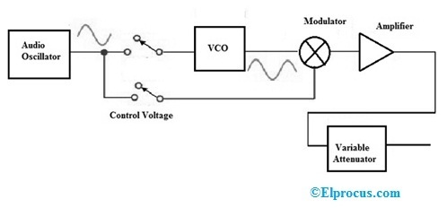
Fm Basic Frequency Modulation Components Testing Of Fm Transmitter
![]()
Infrared Intrusion Barrier
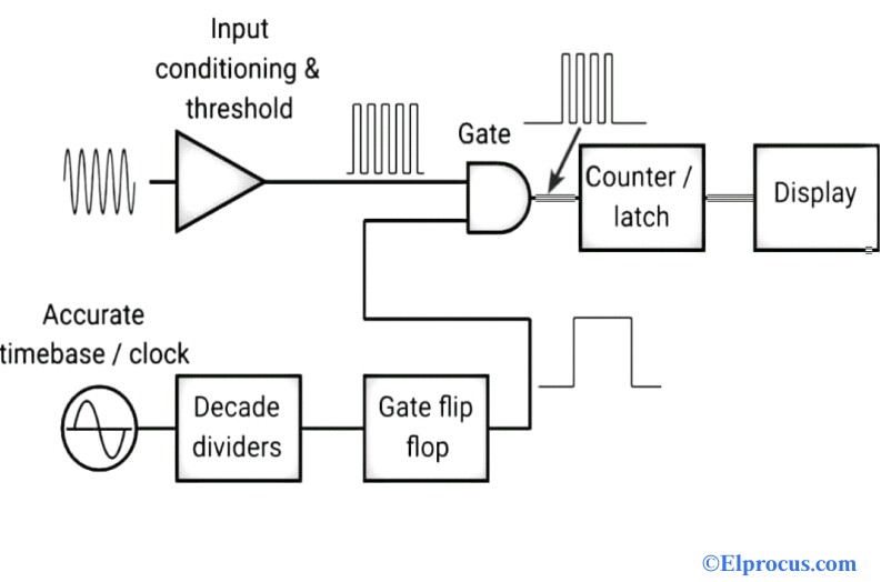
Frequency Counter Block Diagram Circuit Types And Its Applications
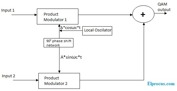
Quadrature Amplitude Modulation Block Diagram Its Working Principle

Transmitter Receiver An Overview Sciencedirect Topics
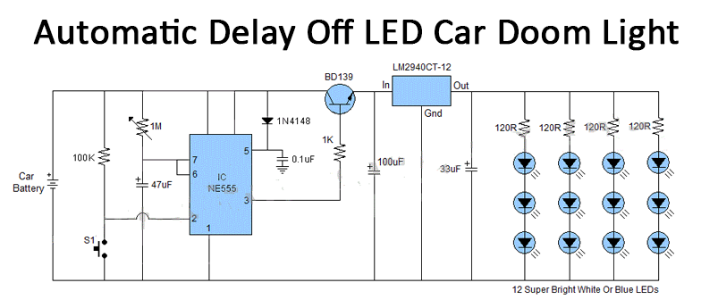
Perhaps The Best 124 Light Emitting Diode Circuit Diagram Homeicon Info
![]()
Adaptive Delta Modulation Block Diagram And Applications
What Is The Difference Between A Schematic Diagram And A Pcb Layout Quora
![]()
1khz Ir Transmitter Circuit
Pira Cz Stereo Encoder For Fm Broadcasting
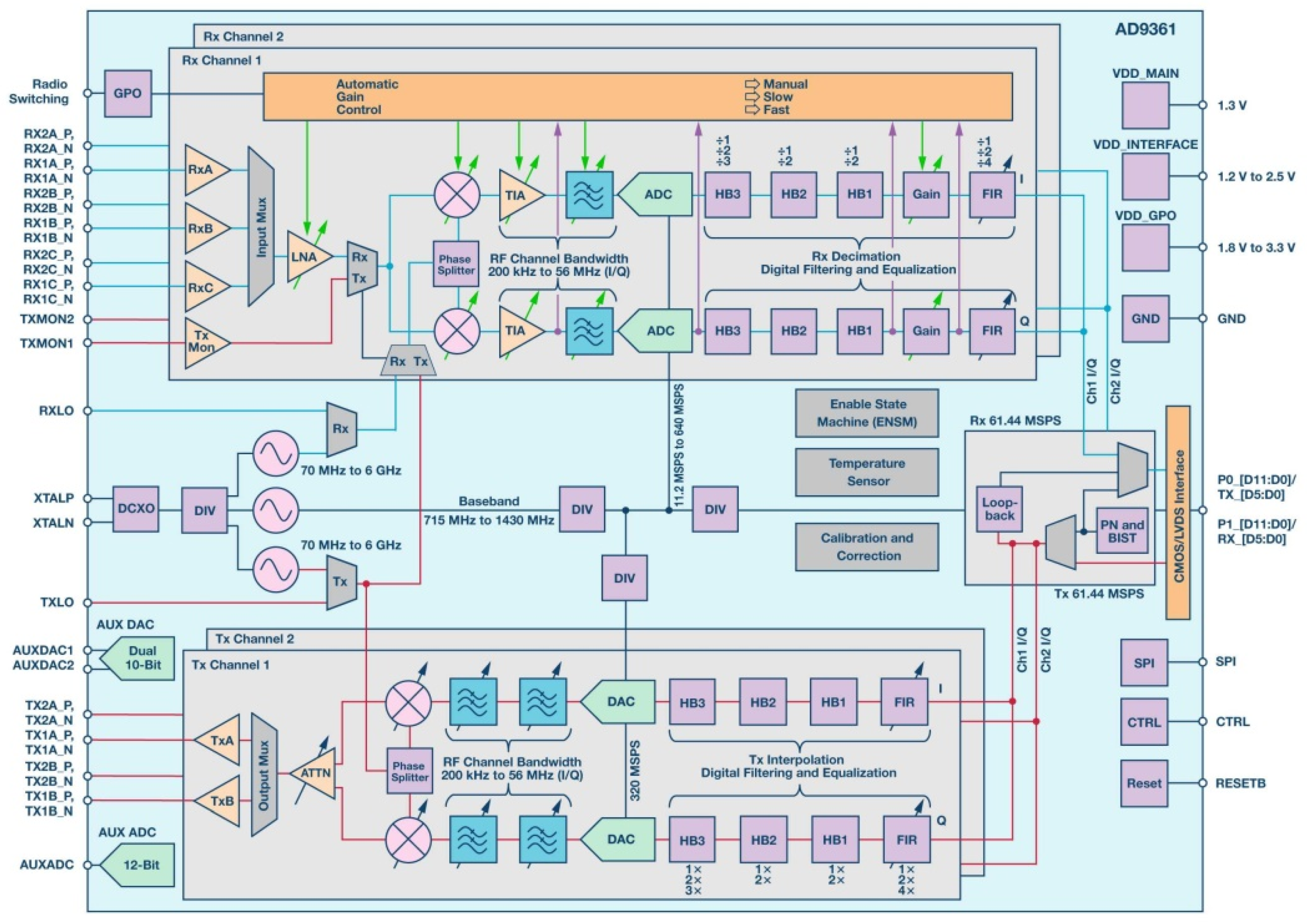
Aerospace Free Full Text Heavy Ion Induced Single Event Effects Characterization On An Rf Agile Transceiver For Flexible Multi Band Radio Systems In Newspace Avionics Html

Hp 456a Current Probe Repair To Create Is To Live
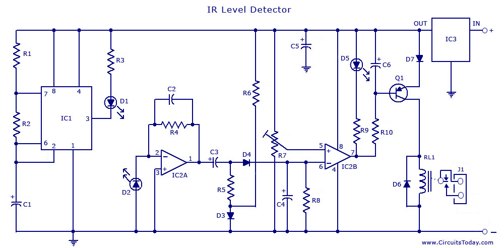
Infrared Ir Sensor Circuit Detector Circuit Diagram Using 555 Ic
Pira Cz Stereo Encoder For Fm Broadcasting
![]()
Perhaps The Best 124 Light Emitting Diode Circuit Diagram Homeicon Info